


Fais fab chips txuas nrog sab nraud circuits los ntawm cov khoom ntim, and their performance depends on the support of the product packaging. In high-power situations, power chips are typically packaged as power components. Chip interconnection describes the electrical link on the top surface area of the chip, which is generally aluminum bonding wire in standard components. ^
Conventional power component bundle cross-section
At present, industrial silicon carbide power components still primarily make use of the packaging modern technology of this wire-bonded standard silicon IGBT component. They face issues such as big high-frequency parasitic criteria, inadequate warmth dissipation capability, low-temperature resistance, and insufficient insulation toughness, which restrict making use of silicon carbide semiconductors. The display screen of exceptional performance. In order to resolve these troubles and completely make use of the big potential benefits of silicon carbide chips, many new packaging innovations and services for silicon carbide power components have emerged recently.
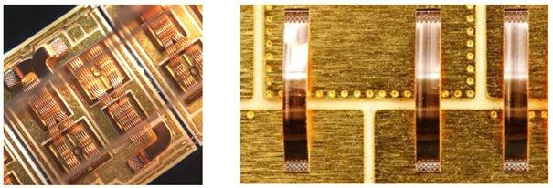
Silicon carbide power module bonding approach
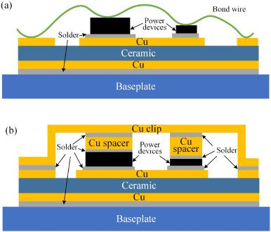
(Figure (a) Wire bonding and (b) Cu Clip power module structure diagram (left) copper wire and (right) copper strip connection process)
Bonding products have created from gold cord bonding in 2001 to light weight aluminum cord (tape) bonding in 2006, copper cord bonding in 2011, and Cu Clip bonding in 2016. Low-power tools have actually developed from gold cords to copper wires, and the driving force is price reduction; high-power tools have actually developed from aluminum wires (strips) to Cu Clips, and the driving force is to boost item efficiency. The higher the power, the greater the requirements.
C, u. Clip Bond, C, l. i, p:
1. The connection in between the chip and the pins is constructed from copper sheets, y, o, g. f, a special plan resistance worth, t, o.
2. o, j.
3. The product look is completely regular with normal products and is mostly utilized in servers, portable computer systems, batteries/drives, graphics cards, motors, power products, and various other fields.
Cu Clip has 2 bonding methods.
All copper sheet bonding method
Both the Gate pad and the Source pad are clip-based. This bonding technique is much more costly and complicated, yet it can accomplish much better Rdson and much better thermal results.
( copper strip)
Copper sheet plus cord bonding technique
The resource pad utilizes a Clip approach, and the Gate makes use of a Cord approach. This bonding method is somewhat cheaper than the all-copper bonding approach, conserving wafer area (appropriate to really small gateway locations). Cov txheej txheem tsis tshua muaj qhov nyuaj dua li tag nrho-tooj liab txoj kev sib txuas thiab tuaj yeem ua tiav ntau qhov zoo dua Rds (on) thiab ntau qhov txiaj ntsig thermal zoo dua.
Tus neeg muag khoom ntawm tooj liab sawb
TRUNNANO yog tus xa khoom ntawm surfactants nrog ntau dhau 12 years experience in nano-building energy conservation and nanotechnology development. It accepts payment via Credit Card, T/T, West Union and Paypal. Trunnano yuav xa cov khoom rau cov neeg siv khoom txawv teb chaws los ntawm FedEx, DHL, los ntawm huab cua, or by sea. Yog tias koj tab tom nrhiav tooj liab ib ounce, thov koj xav tiv tauj peb thiab xa ib qho kev nug.
Nug nrog peb